The University Rover Challenge takes place once a year, at the Mars Desert Research Station in America. It requires teams to construct autonomous exploration robots thats compete in a number of tests requiring object manipulation, life detection, and autonomous traversal. For RMIT’s first entry into the URC we needed a software system that could be implemented quickly, but wouldn’t hamper later development with architecture redesigns.
As the teams first software lead, it was my job to establish requirements and come up with an initial concept. With help from some academics, other students, and studies of previous URC entries I developed an onboard computer software and hardware architecture.
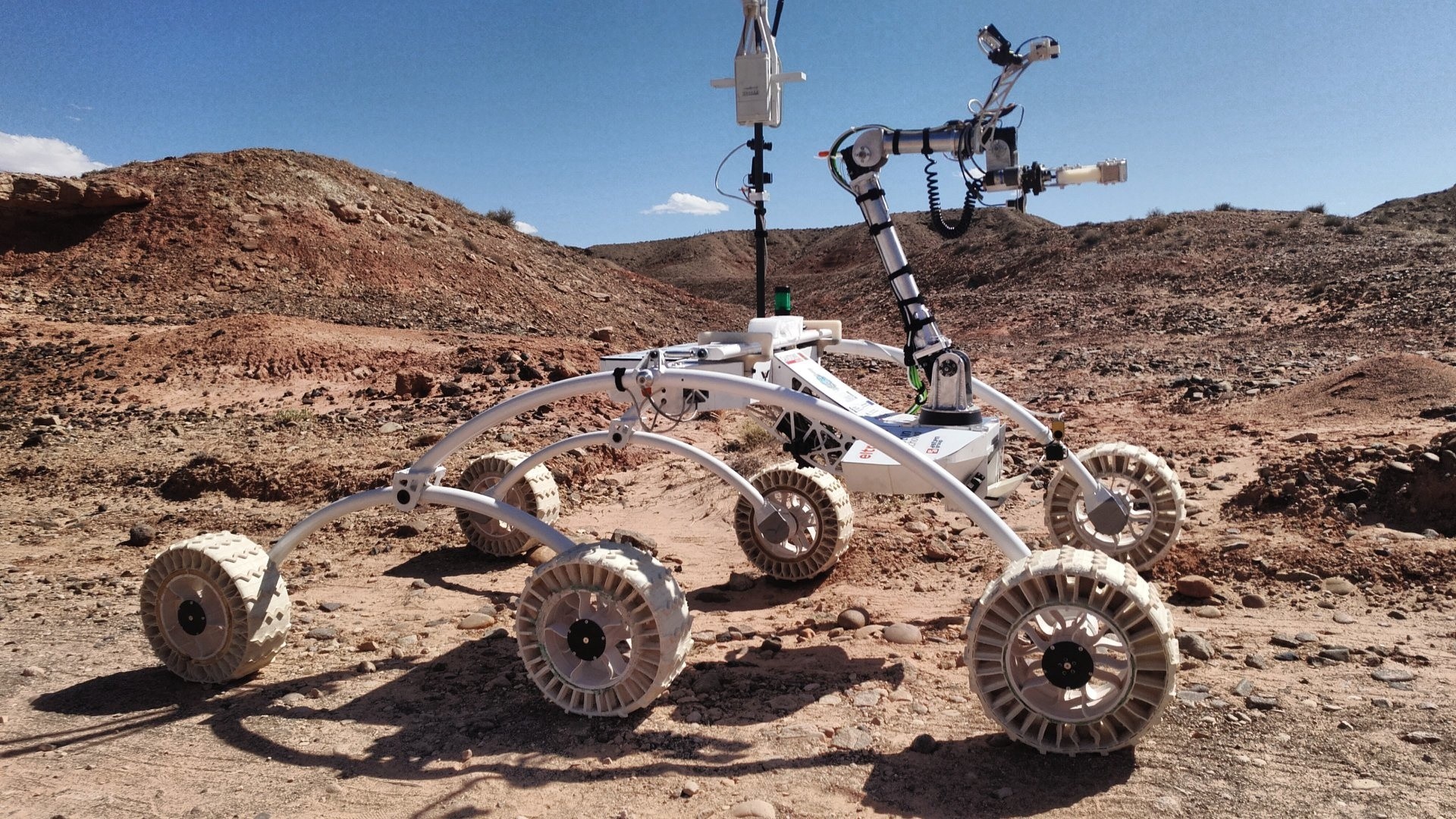 The Politechnika Częstochowska Team Rover. Note the extremely compact body with high ground clearance. Internally, they also use custom PCB embedded controllers for all their computer peripherals. Maybe in a few years…
The competition involves both manual control and autonomous control stages, so control over rover systems such as the wheels needed to be shared. We had less then a year before the design had to be entered into the URC, so time was short. And meeting up in person was difficult for several reasons.
The decision to separate the computer system into a embedded platform controller and a multitasking OS main processor was made early on. As the complexities of dealing with realtime tasks on a device that also supports a novice development environment (ie python) were too high. Linux with a realtime kernel patch was evaluated for this.
 RMIT’s rover onboard system diagram
To support two separate teams (software and embedded) working on these two computers, two separate wireless links are used. One low bandwidth command link is used for the platform controller, which acts as a bus to distribute the messages coming in from the ground as well as internal messages. The high bandwidth link is transmit only, and is used for video, autonomous map data and computer debugging output.
After the initial design for the above system was created, my focus moved to the software team specific areas. Given the above system, the following main computer requirements were distilled for the software team:
Requirements
Main Computer Software System
- Rapid prototyping, the system must be able to be developed quickly.
- Software components individually testable, without access to real hardware. Software team members would need to work in parallel to meet the deadline.
- The system layout should last multiple competitions, so the underlying design should be adaptable enough to facilitate this. Initial software components will be low quality due to the time constraints, and their replacement is inevitable.
- Latency is very important for components involved with manual control, otherwise its not to be worried about at this stage. (Video Streaming, Platform Controller)
- Issues with individual software components should be recoverable, without manual intervention. Because radio contact to the rover is not guaranteed. These issues may take the form of crashes or hangs from any level of the software stack.
Main Computer Hardware
- Due to the latencies required, hardware accelerated video encoding must be present on the main processor.
- The computer must have hardware CAN support
- Some form of hardware acceleration for general purpose matrix operations is required. As deep learning and image processing task latency can benefit significantly.
Solutions
Summary
- Nvidia Jetson SBC for main computer
- Have language agnostic IPC (generally linux IPC).
- Have a failsafe watchdog, so crashes or lock ups should be externally detectable and will cause the component to be killed and restarted. This will be a part of the C&C interface.
- The individual software components must be able to save and restore state on hard reboot or crashes. To allow recovery of partially completed missions.
 RMIT’s rover software system diagram, the product of many iterations
Each component inside the Jetson, except for the Command and OS components, functions in a similar environment. With their startup, command input/output and monitoring managed by the central Command component, which has access to the serial link or rover bus. The system is arranged like this to allow each of the managed components to be isolated, and hence developed independently of the hardware and each other. To further remove interdependence of components, only native Linux methods of inter-process communication are used. Such as memory mapped files and stdin/stdout. This allows different languages and libraries to be used for each component without anyone having to make allowances in their component for features or libraries that may not be available in other components.
Read on for a further explanation of the various software solutions and how they are implemented.
Features
State Storage and Recovery
The components store their state in a particular location on disk with enough detail to allow them to finish a partially completed mission even if the power to the system is interrupted. The state file(s) is used to convey parameters to the component as well as to store those parameters if the system is interrupted. The file(s) are therefore managed by the command component, which also uses them to infer whether the component should be running or not on boot. There are two kinds of state that will be stored, state known at startup (probably arguments etc). And state generated by the program as it runs, such as a map of the surroundings. These two should be separated.
Component Monitoring
The Command component knows if each managed component is supposed to be running or not. And takes actions to restart the process if it exits or is detected to have failed. If a particular message is not observed in the stdout frequently enough the component will be assumed to have crashed/frozen/hung. (The watchdog message is currently “woof”). The actions the Command process takes to restart the others are progressive, with some of the components state being deleted if it fails again.
Forwarding Input and Output
Control of each managed process is done through stdin and stdout (no use for stderr yet), because this mechanism is common to all userspace processes (even on windows I think). The Command process functions almost as a shell for the ground station, with the purpose of the interface being to allow the state (and settings) of each managed component to be changed, even while they are running, and to allow output (usually debugging text) to be forwarded back to the ground station from a managed component. Internally there may be some information that needs to be moved from one process to another within the managed environment. It doesn’t really fit very well with the intended purpose of the Command process, but such a thing could easily be done. If the amount of information being exchanged is small. However larger bandwidth connections, such as video, should sort out their own IPC (eg memory mapped files).
Remote Development
Once the Managed components are working in isolation, testing and development will need to be done using the Jetson itself. This could be difficult for some who are physically far away from the Bundoora lab. To resolve this, the Jetson will be exposed to the internet so that team members can develop on it remotely. Using a cloud server to maintain a constant connection to the Jetson through the NAT of whatever network it’s in. Forwarding connections to servers like SSH, SFTP and some form of remote desktop.